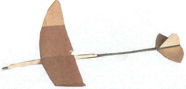
Introduction
A combination of launching height and sink rate is what determines the how long a glider will stay aloft (glide time assuming no thermals). If one assumes a particular height then the sink rate of the glider is what determines the time a glider stays up. Understanding the parameters/issues that increase the sink rate is the ultimate goal. This paper is applicable to both Indoor Catapult gliders and Outdoor Catapult gliders events since the fundamental laws of physics stay the same. This paper assumes still air and does not take into account thermals.
Glide Angle
First one must start with a simplified picture of the forces on a glider as it descents down. We will assume a constant sink rate with the glider traveling in a straight line, in calm air. The diagram below shows the force on the glider at the CG (center of gravity).
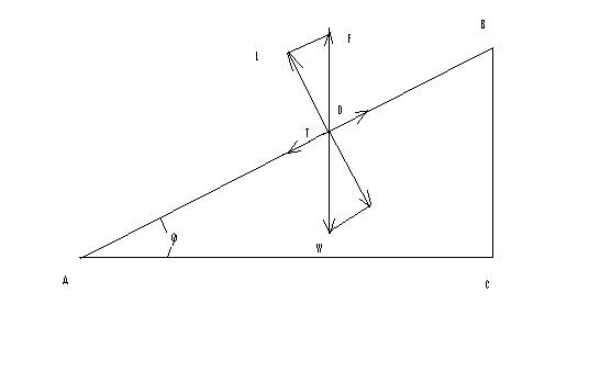
W is the weight of the glide
j is the angle of constant descent
L is the lift force on the glider
D is the drag of the glider
T is the thrust being applied to the glider
F is the resultant force or Lift and Drag vector
For constant descent or for equilibrium conditions:
T=D
F=W
Triangle ABC is similar to Triangle DLF
Therefore from trigonometry; similar triangle theorem;
Angle CAB is equal to Angle FDL=j
Distance AC/Distance BC= L/D
The Lift Force, L, is equal to;
L=1/2 CL*r* A*V^2 (1)
And
The Drag Force, D, is equal to;
D=1/2*Cd*r* A*V^2 (2)
So the ratio of L/D is Cl/Cd
And the glide angle is
j=acrtan(Cd/Cl) (3)
So it is very interesting to note that the glide angle is only the ratio of Cl (lift Coefficient) and the Cd (drag coefficient).
Horizontal and Vertical Velocities
The power or thrust, which moves the glider through the air, comes from the potential energy, the glider releases. This is the component of weight from the loss of attitude. In equilibrium conditions, T=D, therefore:
T=D=1/2*Cd*r* A*V^2 (4)
Which can be rewritten as:
V=(2*T/(Cd*r* A)^.5 (5)
We can also calculate the velocity from the lift equation:
L=1/2* CL*r* A*V^2 (6)
Which can be rewritten as:
V=(2*L/(Cd*r* A))^.5 (7)
Since L=Wcosj we can substitute in and get the following equation:
V=(2*W*cosj /(Cd*r* A))^.5 (8)
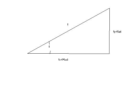
From the velocity triangle above we can see that;
V=Vx/cosj (9)
V=Vy/sinj (10)
Substituting into equation (8) we conclude:
Vx= cosj*( 2*W*cosj /(Cd*r* A))^.5 (11)
And
Vy= sinj*( 2*W*sinj /(Cd*r* A))^.5 (12)
Now we have two equations that will predict the horizontal and vertical velocities of the glider. The sink rate is basically Vy, the vertical velocity of the glider.
Minimizing the Sink Rate
In gliders we want to make the vertical velocity down as small as possible. So to achieve this we must take equation (12) and understand how to make Vy as small as possible.
First we can use equation (3) and rewrite it as:
Sinj/Cosj=Cd/Cl (13)
Subsitituting equation (13) into equation(12) we get the following:
Vy= Cd*cosj/Cl*( 2*W* cosj /Cl*r* A))^.5 (14)
If we assume a small angle of descent, cosj (becomes 1 for small angles) and equation becomes;
Vy= Cd*( 2*W*/(Cl*r* A))^.5 (15)
So we simplify and
Vy=1.41* Cd*W^.5/ (Cl^1.5*r^.5* A^.5) (16)
If we assume a specific design with a fixed weight /area and same air density then :
Vy proportional to Cd/Cl^1.5 (17)
Or to minimize the sink rate, the ratio Cl^1.5/Cd must be as large as possible.
Determining Cl and Cd
One may wonder how to obtain reasonable numbers for Cl and Cd. Airfoils have corresponding data, which are referred to as polars. Polars are basically x-y graphs of Cl vs angle of attack and Cd vs angle of attack. Or quite often polars can be Cl vs Cd. Polars can either be measured in wind tunnels or theoretically calculated. Since I could not find any wind tunnel testing on model glider airfoils especially at the reynold’s numbers of interest, I resorted to theoretically calculations. Xfoil is a free 2D software package available on the Internet from Mark Drela. Mark is a professor at MIT and a well-known modeler.
Below are Polars for Stan Buddenbohm’s Lit’l Sweep airfoil generated by Xfoil.
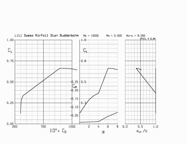
Angle of Attack
Now that the polars are generated from the particular airfoil shape one must determine at what angle of attack will minimize the sink rate. One can calculate the Cl^1.5/Cd from the above polars to obtain an optimum angle of attack is around 4 degrees.
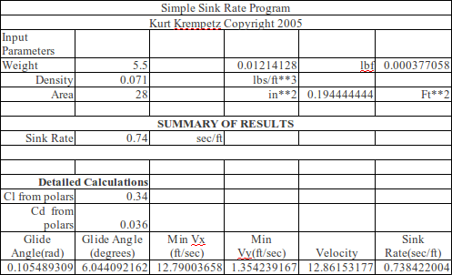
Simply Spreadsheet to Calculate Sink Rate
Using the above equations an Excel spreadsheet was developed to calculate a glider’s sink rate. Some typical number for a standard catapult glider where inputted into the spreadsheet with the calculated xfoil Coefficient of lift and Coefficient of drag of a wing’s airfoil.
Conclusions
Some equations and spreadsheets were developed to predict sink rate or glide times. The sink rate these equations and spreadsheets appear to give are reasonable with actual times that are achieved by gliders. It is clear further work is needed to understand how to predict sink rates. This was a very simple model in which only the wing (area and airfoil) and weight of the model was included in the calculations. The spreadsheet needs to be developed to incorporate the other factors, which include the elevator, rudder and fuse.